
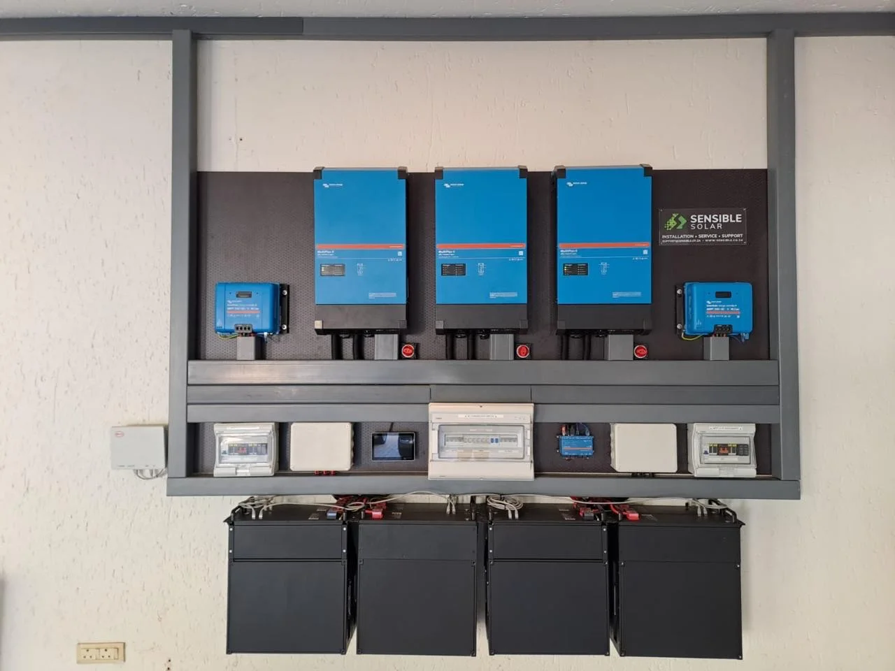
A good cell is only part of a good battery system
When a business compares batteries, the cell manufacturer and chemistry are useful questions, but they are not a complete quality assessment. Cells, connections, sensors, balancing, switching hardware, firmware and inverter integration must work together. A recognised cell name cannot establish the performance or serviceability of the finished installation.
Ask for the exact battery model, its applicable documentation and the proposed system configuration. The useful question is not simply whether it has a battery management system, or BMS, but what that BMS measures, controls and records.
Individual cells matter more than the pack average
Cells connected in series contribute to the battery's total voltage. One cell can approach its operating limit while the total still looks unremarkable. That is why individual cell monitoring matters: an average cannot reveal every outlier.
Lithium iron phosphate, usually called LFP, has a relatively flat voltage curve through much of its charge range. Voltage alone is therefore a poor basis for a precise remaining-energy claim. State of charge is an estimate produced by the monitoring system; measurement accuracy, configuration and synchronisation matter. A display reading 100% is not an independent capacity test.
Balancing helps cells work together; it does not renew them
Small differences between cells can cause one to reach a charge or discharge limit before the others. Balancing manages differences in their charge state. Passive balancing dissipates energy from higher-charge cells; active arrangements transfer energy. The implementation, available balancing current and conditions under which it operates matter more than the label alone.
Ask how normal operation gives this particular product the opportunity to balance. Do not copy another battery's absorption time or voltage settings. Persistent imbalance needs diagnosis, not repeated attempts to force the pack higher. Balancing is not a repair for a damaged cell or a guarantee that lost capacity will return.
Separate normal control from protective shutdown
The system should normally operate within the manufacturer's limits rather than repeatedly hitting emergency protection. Establish which components detect excessive cell voltage, low voltage, temperature and current, and which devices actually stop charging or discharging. Some products integrate these functions; others require an external BMS and controlled equipment.
A BMS also does not replace correctly designed fusing, isolation, cabling or the installation's wider protection. Ask the installer to explain the safe response to faults. Do not bridge protection, alter service-port settings or bypass a BMS to recover a stopped battery. Recovery must follow the specific manufacturer's procedure through a suitably qualified person.
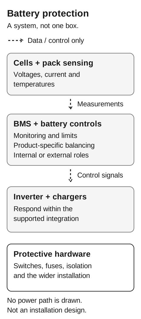
Read the text explanation and sources
- Cell and pack sensing supplies information such as voltages, current and temperatures.
- Battery-management functions include monitoring and limits, with product-specific balancing; the roles may be internal or external to the pack.
- Compatible inverter and charger controls must respond through the supported integration. The drawing does not imply that every external charger is automatically controlled.
- Protective switches, fuses, isolation and the wider electrical installation remain separate design responsibilities. No power path or all-current-through-BMS assumption is drawn.
Sources supporting this illustration
A communications cable is not proof of compatibility
In a supported managed-battery system, communications can convey a charge voltage limit, charge current limit and discharge current limit, often abbreviated CVL, CCL and DCL. These limits may change with battery conditions. The inverter and chargers need to interpret and respect the supported control scheme.
A matching CAN socket does not prove that two products speak the same protocol. Verify the exact battery, inverter, controller, firmware and minimum configuration against current manufacturer guidance. Include every charging path in the review: an unconnected charger is not necessarily controlled by the main gateway.
Commissioning should establish what happens when communications fail or a limit is reduced, using the manufacturer's approved test procedure. It should not rely on an assumption that either the communications link or the battery's final protective switch makes every combination acceptable.
Request evidence that will help when something goes wrong
A cloud dashboard can be useful without showing everything the battery measures internally. Ask which cell readings, temperatures, alarms and current limits are available locally, which are retained remotely, and how timestamps and exports work. Sensor sampling, communications updates and cloud logging are different things; a smooth graph does not prove there was no brief event.
- Record models, serial numbers, firmware and the approved integration at handover.
- Keep commissioning results and access arrangements with the system documentation.
- Agree who reviews alarms, who responds, and what requires a site visit.
Start with the installation you need to support
Send us the proposed or existing equipment details, your business location and the operational problem. We can establish whether the next step is a compatibility review, a broader system assessment or a site visit.
Sources and further reading
- Analog Devices: fuel gauging LFP batteries and the limits of voltage-based estimates
- Texas Instruments: monitoring, safety and balancing in battery energy storage
- Victron Lithium Smart introduction: an example of battery monitoring with an external BMS
- Victron Lithium Smart appendix: product-specific cell balancing
- Victron Cerbo GX: DVCC limits and supported control arrangements
- Victron Lynx Smart BMS NG: monitoring data and communication paths
See the approach in practice
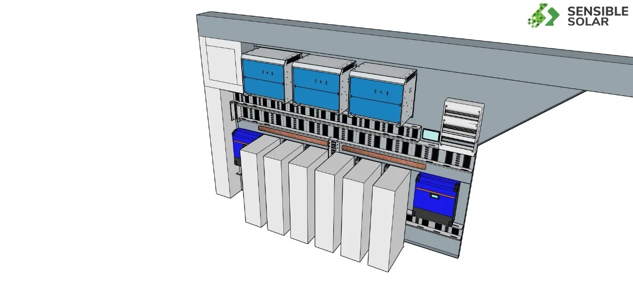
Solar and storage
From concept to installation
A 45 kVA project with 112 kWh of energy storage.
See the project